4.
4-antenna
phased array at 2 MHz with fully steerable beam
5.
8-antenna
phased array at 4 MHz, communications receiver performance.
A side
project might be the use of beam synthesis for transmitting.
AM Broadcast Software Radio Project
This article
describes the equipment I used to study an all-software AM Broadcast Band
radio. Since I consider my efforts to
be just a feasibility study, I will not present this project as a construction
project. However, I hope there is
enough information here to allow someone to reproduce my work, or at least
point out any serious flaws.
Since completing
this work, I believe there is a better approach to electronic beam steering,
which reduces the amount of computation required with only a slight increase in
the amount of hardware. I cover that
idea at the conclusion.
Besides
learning about digital signal processing, I also had to learn how to perform
fast, real-time I/O with a modern PC, and design and build high performance
filters. Fortunately, readily available
free (or limited time trial) software is available to assist with all of these learning
curves.
Hardware
The AD6644
is available on an evaluation board, the AD6644ST/PCB, which sells for $200,
direct from Analog Devices[3]. Besides the ADC chip, this board provides an
oscillator; BNC connectors for RF input and external clock input; proper input
impedance matching; and buffered parallel output on a 50-pin header. You can order one with a credit card (Figure 1).
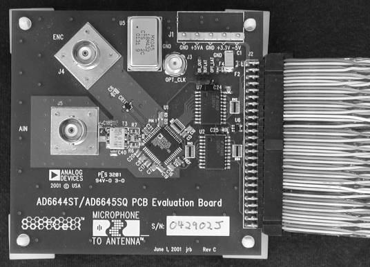
Figure 1 - Analog Devices AD6644ST/PCB Evaluation Board
The
AD6644ST/PCB requires both 5 volts and 3.3 volts DC, preferably regulated with
linear regulators to minimize noise (Figure 2). I built a
small board with a 7805 regulator for 5 volts and an LM317 programmable regulator
for 3.3 volts. The board plugs into a
spare floppy disk power connector in the PC.
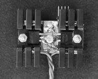
You can see the male connector peaking out from under the heat sink in Figure
3. Three braided wires
carry the two voltages to the evaluation board’s pluggable terminal strip.
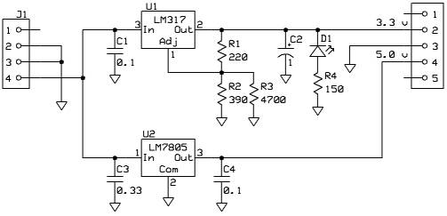
Figure 2
- Voltage Regulator Circuit for AD6644ST/PCB
The
evaluation board comes equipped with a 66.666 MHz modular oscillator, a CTS
Communications Components MX045[4],
installed in a socket. I ordered
several of these oscillators for different frequencies from Digi-Key[5],
since they only cost around $3 each.
The data sheet for the AD6644 states the minimum clock speed is 5
MHz. Since that speed is faster than my
PC can process, I had to divide the clock rate down. I used a 74HC161 binary counter chip to divide the clock by 8 or
16. So, a 32 MHz oscillator divided by
8 gives 4 MHz, which is about the upper limit of processing speed on the
PC. Note that the PC ignores 7 out of 8
samples. In other words, the clock
divider decimates the sample stream.
Therefore, the analog low-pass filter that precedes the analog to
digital conversion step must roll-off frequencies above 2 MHz. You can consider the amount of roll-off to
be the amount of receiver image rejection.
Four million 14-bit numbers per second is
faster and wider than the PC parallel port, so I needed some sort of parallel
interface device. Furthermore, the parallel interface device will need a first
in, first out (FIFO) buffer to hold samples until the PC can transfer them to
main memory.
Figure 3
- Voltage Regulators
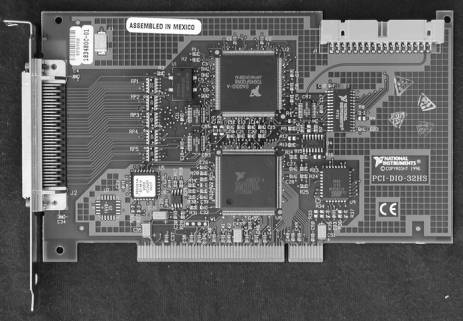
Initially, I used a National Instruments
PCI-DIO-32HS[6] (Figure
4), which is a 32 bit parallel interface
Figure 4 - National Instruments PCI-DIO-32HS Digital IO Board
that plugs
into the PCI bus, and promises 20 MS/s throughput. However, that 20 MS/s turns out to be the peak throughput, and
the average, sustainable throughput is really about 3-4 MS/s, depending
slightly upon the speed of the host PC.
Furthermore, the PCI-DIO-32HS costs $995 and requires a special cable
that costs $125. The card and cable use
high-density 68-pin D-sub connectors, which are not wired the same way as a
SCSI connector (too many signals), which prevents the use of commercial
adapters.
I built an
adapter on a small piece copper clad epoxy fiberglass (Figure
5). The 50-pin header
connector and the 68-pin, high-density, D-sub connector are both directly
soldered to the circuit board with their ground pins. I put the sample clock divider on the adapter board as well,
mounted “dead bug” style (Figure 7).
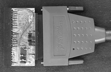
Figure 5
- Adapter from AD6644 Evaluation Board to PCI-DIO-32HS Cable
After
struggling with the PCI-DIO-32HS for a while (it did work, just not as
well as I hoped), I found a nifty device made by Techniprise. They build a device they call the PCI
ProtoBoard[7]
(Figure 6). This

Figure
6
- Techniprise PCI Protoboard with 50 Pin Wire Wrap Header
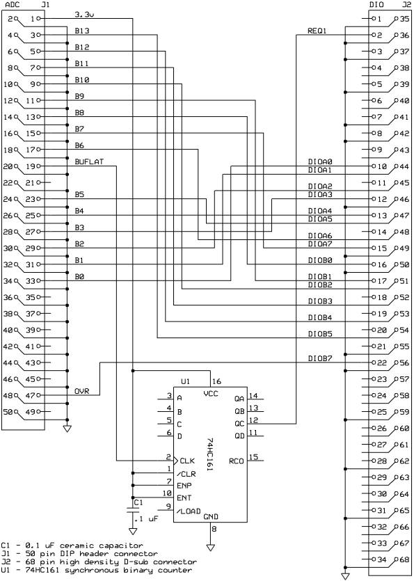
Figure 7
- AD6644 Evaluation Board to PCI-DIO-32HS Adapter
$395 device
marries a Xilinx field programmable gate array (FPGA) chip and a high
performance PCI controller on a board with additional space for wire-wrap style
prototyping. The ProtoBoard makes
available 64 bits of interface signals, on-board and external clocks, and
another 24 bits of control signals. The
Xilinx XC2S200 provides 200,000 gates and 56,000 bytes of RAM. I expected that I could learn to program the
FPGA chip to function as an asynchronous FIFO and clock divider.
The only
other digital hardware required, besides the PC itself, is a 50 wire flat
cable, and a 50-pin header to mount on the PCI ProtoBoard. The wire wrapping connects the 14-bit output
from the ADC to
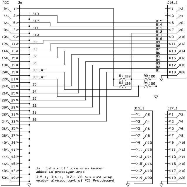
Figure 8 - AD6644S/PCB to PCI-Protoboard Adapter
14 I/O pins,
and connects the data strobe from the ADC to the external clock input of the
PCI ProtoBoard (Figure 6
and Figure 8). In order to
get a clean clock signal, I had to put a terminator network on the PCI
ProtoBoard end of the flat cable. I
used a spare flat cable connector, soldering the resistors directly to the
connector's pins to minimize lead length (Figure 9). Since the
ADC board supplies the strobe output on two adjacent pins, I used two networks,
even though only one output is connected.
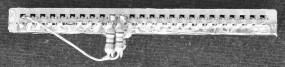
Figure 9
- Clock Termination Resistors on Header
I also built
a "switches and lights" I/O board to attach to some of the 24 control
bits, so I could interact with the FPGA while learning to program with
Verilog. This board connects via a 20
wire flat cable to
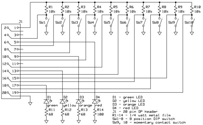
Figure 10
- Switches and Lights I/O Board Schematic
one of the
20 pin headers on which the PCI ProtoBoard supplies a subset of the 24 control
bits (Figure 10 and Figure
11). Once the FIFO
firmware was completed, the I/O board is no longer really necessary. While FPGA programming is not the
focus of this article, I must suggest that field programmable gate arrays could
be a very useful ham radio technology.
I recommend Al Williams’ web site, especially his Getting
Started with Programmable Logic[8].
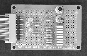
Figure 11
- Switches and Lights IO Board
Any digital
radio requires some sort of analog filter prior to analog to digital conversion
to prevent aliasing. Currently, I'm
using a tunable preamplifier. The tuner
substitutes for a low-pass filter while the preamplifier scales the analog
signal so that the maximum value does not exceed the 2.2-volt peak-to-peak
limit of the AD6644. If there was a
permanent application of this most expensive AM broadcast radio, I would use
this 5 pole elliptical low-pass filter and an active antenna in place of the
tunable preamplifier (Figure 12).
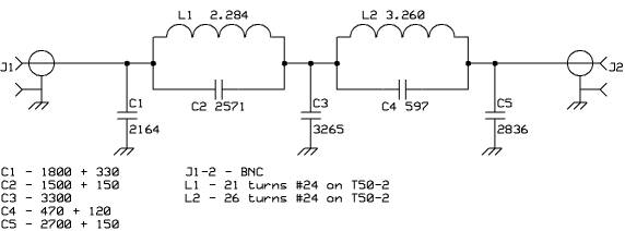
Figure 12
- Low-Pass Filter
The PC
itself consists of an Asus A7V333 motherboard with an Athalon 2400 XP+ (2.053
GHz clock, 333 MHz front side bus) microprocessor, 256 MB of DDR RAM, and a
vanilla 30 GB hard disk, dual bootable into either Windows 2000 or Red Hat
Linux (kernel 2.4.18). Note that
Windows 2000 was installed with the "standard" kernel, as opposed to
the ACPI kernel, so that the assignment of IRQs is somewhat under the control
of the user. The ACPI kernel insists on
using a single shared IRQ for all PCI based I/O on the system (IDE, USB, etc.,
as well as the parallel I/O card) whereas a high rate I/O card really wants its
own IRQ.
Software
The first
version of the software used the National Instruments supplied Windows 2000
driver for the PCI-DIO-32HS card and a C++ program feeding DirectSound (part of
DirectX) that could receive up to 1 MHz (2 MHz sampling rate). This version demonstrated that an
all-digital radio was feasible, and that the PCI-DIO-32HS was horribly slow.
The second
version of the software continued the PCI-DIO-32HS, but used RTLinux[9],
kernel 2.4.4, a custom driver, and essentially the same C++ program feeding the
Advanced Linux Sound Architecture driver for my sound card. After considerable effort to get direct
memory access (DMA) working and very careful performance tuning, this software
could receive to 1.5 MHz (3 MHz sampling rate).
The third
version of the software used the PCI ProtoBoard under Windows 2000 and the same
C++ program now reconfigured as a direct conversion receiver feeding
DirectSound. Because of the much larger
FIFO implemented via the FPGA, this system can receive to 2.3 MHz.
The first
two digital receivers implemented a super-heterodyne receiver in software. The super-het design requires many stages,
but avoids the mental problems that arise concerning complex frequency (Figure 13).
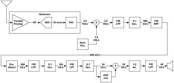
Figure 13
- Super-Heterodyne Receiver Block Diagram
Once one
mentally conquers complex frequency, the direct conversion approach becomes the
obvious choice (Figure 14). I also
choose a sampling frequency that evenly divides down to the 48 kHz audio
sampling rate, which eliminates some steps.
Note that the 64:1 decimation stage is really a 4:1 stage followed by a
16:1 stage.
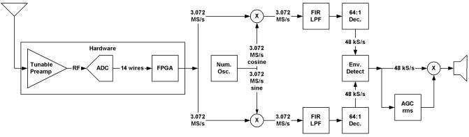
Figure 14
- Direct Conversion Receiver Block Diagram
The actual
digital signal processing part of the software turns out to be very
simple. A big loop moves samples one at
a time through mixing, filtering, decimation, and detection stages. The end result is a sequence of audio
samples. Note how much the flowchart
looks like the block diagram (Figure 15).
Mixing means
to multiply one signal by another. In
analog signal processing, one mixes by applying the two signals to a non-linear
stage. In digital signal processing,
one mixes by multiplying the sample value for one signal by the corresponding
sample value of the other signal. Thus,
a local oscillator is simply one second’s worth of samples stored in a buffer.
Finite
impulse response (FIR) filters in digital signal processing correspond to
passive analog filters. FIR filters
require buffering a set of some number of previous samples. When a new sample becomes available, the new
sample replaces the oldest sample. Then
the set of samples is multiplied by a set of coefficients and the products
summed, yielding a new current sample.
Decimation
doesn't have a handy time domain analog, except that decimation occurs in
digital processing at the same point in analog processing where bandwidth
decreases. Decimation merely requires
all but every nth sample be ignored (jump to the bottom of the big loop).
Envelope
detection of a complex series merely requires computing the magnitude of the
complex value, which is the square root of the sum of the squares of the real
and imaginary values (good old Pythagoras).
The final
step deposits each sample, now representing audio, in the DirectSound sound
buffer.
A proper
receiver has automatic gain control and a signal strength meter. Signal strength requires computing the RMS
average of many samples over some period of time, for example, 0.2 second for
attack, and 0.5 second for release.
When I get the gain properly computed for each stage, the computed
signal strength should correspond to exactly the absolute signal strength in
microvolts.
The rest of
the program consists of code to configure the software for various tests. One configuration replaces the retrieval of
samples from the hardware with the retrieval of samples from a pre-computed
buffer. I call this signal generator
mode. Another configuration skips all
processing and just writes samples directly to a file. Other options allow recording the sample
stream at various points in processing, in effect providing a signal tracing
capability.
The final
bit of software complexity required separate programming threads, one thread to
drive the data acquisition process (make PCI ProtoBoard driver calls) and
another thread performs the signal processing.
The main thread watches for keystrokes, which allows the user to tune
the radio. Whenever the user types the
"a" key, to tune up 10 kHz, or the "d" key to tune down 10
kHz, the program re-computes the one second long local oscillator sample
buffer.
Tools and References
I strongly
recommend Understanding Digital Signal Processing by Richard G. Lyons[10]
for a very clear development of the concepts of digital signal processing. I wish I had this book when I was in
college.
The most
important tool was a software oscilloscope and spectrum analyzer. ScopeDSP by Iowegian[11]
performs this function very well.
Although the free trial and student versions work well, I eventually
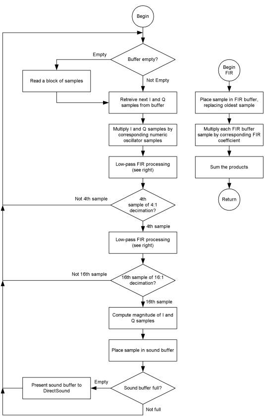
Figure 15
- Flow Chart of Main Digital Signal Processing Loop
purchased
the professional version in order to examine the spectrum of large sample
sets. Spectrum analysis of known
signals helps to find defective filter designs and samples lost during buffer
overruns.
Iowegian
also provides ScopeFIR, which designs FIR filters. ScopeFIR has an effective optimizer that frequently improves
filter performance by reducing the number of taps.
Xilinx
provides ISE WebPack 5.2i[12]
(I used 5.1e), an Integrated Development Environment for their various lines of
FPGAs. WebPack is free, and only a
little obtuse. I took a while to
understand the limitations one encounters using clock signals in an FPGA. FPGAs are not completely arbitrary lumps of
hardware, but very close. The entire
FPGA experience is worth another paper.
Xilinx also
provided an application note[13]
and sample code[14] for
implementing asynchronous FIFO buffers.
Filter
Solutions[15] by Nuhertz
Technologies, LLC is a rather expensive filter design package. However, they provide a 20-day free trial
period. If you plan your usage
carefully, you can use the package to design a couple of filters, and build and
tune them before the trial license expires.
The desirable features of this product are its ability to let you
experiment with component values, its ability to draw attractive schematics of
the final circuit, and the large number of filter designs available in a single
program. I did not compare Filter
Solutions with ScopeFIR for FIR filter design.
I used
Visual Studio 6 to develop console mode programs that run on Windows 2000. I used GNU gcc, make, and the other GNU
command line tools for development of programs that run on Linux. Since this project is just a feasibility
study, fancy graphical programs were overkill.
Results
The AM radio
works. The tunable preamplifier allows
decent reception of only a few 10 kHz channels at a time without retuning. One can hear a separate station on each
frequency, just like with a digitally tuned analog broadcast radio. Since I deliberately design wide filters
with steep skirts, I think AM radio on my computer sounds better than a lot of
stereo systems. I have not yet been
able to try the elliptical low-pass filter in place of the tunable preamp.
The most
significant problem seems to be the fact that the rate of audio samples
produced directly depends upon the sampling clock on the AD6644 evaluation
board, while the sound card has its own clock for moving sound samples from the
sound buffer to the speaker. Thus the
two clocks are not synchronized, and every few hundred seconds, one can hear
the mismatch. The solution to this
problem would be to use the sampling clock derived sample rate for audio
output, but that would require rewriting the sound driver, which so far, I
haven't had time to consider.
Further Work
Since I started
this project, I’ve realized that the best approach to an electronically
steerable antenna system involves the appropriate mixture of hardware and
software. Even though a pure software
approach works, a modest amount of hardware to mix RF down to base-band
considerably reduces the computing burden.
Gerald Youngblood, AC5OG, describes one such circuit[16],[17],[18],[19],
that allows one to mix an HF signal down to baseband while preserving dynamic
range. Then, one can complex sample the
baseband signal with an intermediate-speed, wide ADC. Gerald used a 24 bit sound card.
So, whether
the approach is all-software, or a mix of front end hardware and software, the
next step would be to add a second evaluation board so that two receive
channels can be combined in phase to achieve a steerable receiving beam. Naturally, both ADC boards would have to use
a common clock. Since two ADCs doubles
the throughput, some additional performance gains will be required.
Using
RTLinux with the National Instruments board demonstrated that real time
programming does indeed permit one to extract every last bit of performance
from a machine. Unfortunately, as of
the time of writing, Techniprise had not yet finished their Linux driver, so I
don't know what performance gains are yet possible using the PCI Protoboard.
Credit for
Inspiration
I would like
to thank Dr. Robert S. Dixon and The Ohio State University Radio Observatory
for coming up with the concept of the Argus Array telescope[20]. My efforts thus far basically reapply the concepts
of the Argus Array to ham radio, scaled to a level attainable by an individual.